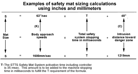
Sizing Your System The following formula is an international draft guideline for the proper positioning and application of safety mats for machine guarding. This formula must be followed for all safety mat applications supplied to the European Community (CE) member nations. CEN is the European Committee for Standardization. Final draft #prEN999 The minimum distance from the danger zone shall be calculated by using the general formula: S=(K x T) +C where: S is the safety mat minimum distance in inches/millimeters in a horizontal plane, from the danger zone to the detecting edge of the safety mat furthest from the danger zone. K is a parameter in inches/millimeters per second, derived from data on approach speeds of the body or parts of the body. K=63 inches/second or 1600mm/second. T is the total system stopping time performance in seconds, which includes activating the safety mat, the mat controller output signal switching device and the time required to stop the machine and remove risk. The activation time of the STTS Safety Mat System including controller is 35 msec (.035 seconds). This amount must be added to the machine stopping time to fulfill the "T" requirements. C is an additional distance in inches/millimeters, based on intrusion towards the danger zone prior to actuation of the protective safety mat equipment. C=48 inches or 1219mm.
Annex
B (informative) Speed of
Approach Stride
Length |


